| The Following 3 Users Say Thank You to jrinconr For This Useful Post: | ||
|
|
2010-10-21
, 10:17
|
|
Posts: 323 |
Thanked: 180 times |
Joined on Oct 2009
@ Gent, Belgium
|
#2
|
very interesting from a scientific point of view. Is there visible practical use during 'normal', non-Matlab/camera assisted lab experiment environment ?
I guess after going through all calibration steps, either on the PC or on -possibly- a N900 version of the calibration tools, using both distortion values into the Fcamera driver might possibly result in better photos. But would the results be visibly clearly better ? Any idea ? Any examples to show made by similar hardware ?
After all we're not talking about the latest 21 Mpixel DSL Canon EON-1Ds beast, this is a 'humble' N900.
Also, are the production parameters of the N900 (or in general) camera module lenses tight enough to do the calibration once and then use it for all N900s ? Or are there normally significant differences between production runs possible ?
Good luck with the calibration anyway, it sure looks you know what you're doing !!
TO come back to your question : Look here
http://wiki.maemo.org/N900_Hardware_VGA_Camara_module
And click through to the datasheet :
Pixel size 2.2 μm x 2.2 μm
There you go Let us know how things are evolving ...
Last edited by Netweaver; 2010-10-21 at 10:18. Reason: typos
I guess after going through all calibration steps, either on the PC or on -possibly- a N900 version of the calibration tools, using both distortion values into the Fcamera driver might possibly result in better photos. But would the results be visibly clearly better ? Any idea ? Any examples to show made by similar hardware ?
After all we're not talking about the latest 21 Mpixel DSL Canon EON-1Ds beast, this is a 'humble' N900.
Also, are the production parameters of the N900 (or in general) camera module lenses tight enough to do the calibration once and then use it for all N900s ? Or are there normally significant differences between production runs possible ?
Good luck with the calibration anyway, it sure looks you know what you're doing !!
TO come back to your question : Look here
http://wiki.maemo.org/N900_Hardware_VGA_Camara_module
And click through to the datasheet :
Pixel size 2.2 μm x 2.2 μm
There you go
 Let us know how things are evolving ...
Last edited by Netweaver; 2010-10-21 at 10:18. Reason: typos
|
|
2010-10-21
, 11:35
|
|
Posts: 32 |
Thanked: 14 times |
Joined on Feb 2010
@ Alcala de Henares, Madrid, Spain
|
#3
|
Originally Posted by Netweaver

in photogrammetry(for near and far objects), we use "metric cameras", and i'll try to use the n900 camera in photogrammetric measurement of small objects
very interesting from a scientific point of view. Is there visible practical use during 'normal', non-Matlab/camera assisted lab experiment environment ?
Originally Posted by Netweaver

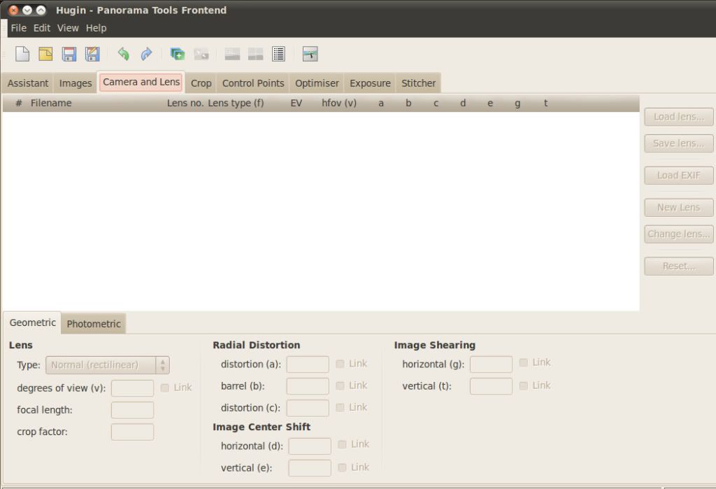
of course, for example, in Hugin software(http://hugin.sourceforge.net/), you can use these parameters to obtain a better pic. or at this abstract you can find other application.http://www.springerlink.com/content/r504u74722775771/
I guess after going through all calibration steps, either on the PC or on -possibly- a N900 version of the calibration tools, using both distortion values into the Fcamera driver might possibly result in better photos. But would the results be visibly clearly better ? Any idea ? Any examples to show made by similar hardware ?

Originally Posted by Netweaver

unfortunately, with non-metric cameras, you need to calculate the parameters for each one.
Also, are the production parameters of the N900 (or in general) camera module lenses tight enough to do the calibration once and then use it for all N900s ? Or are there normally significant differences between production runs possible ?
Originally Posted by Netweaver

I see, but these specs are from frontal camera. 
TO come back to your question : Look here
http://wiki.maemo.org/N900_Hardware_VGA_Camara_module
And click through to the datasheet :
Pixel size 2.2 μm x 2.2 μm

thanks for your comments
See you
Last edited by jrinconr; 2010-10-21 at 12:58. Reason: link forgot


This is a first approach of the calibration parameters of the camera. (you can follow this procedure http://www.vision.caltech.edu/bougue...doc/index.html)
To obtain a more accurate calculation, I need more information, like the pixel size in microns at the sensor.
in theory, with this information, the lens distortion can be corrected. (http://en.wikipedia.org/wiki/Distortion_(optics))
See you!